যখন আপনি একটি জিপিএস পিসিবি ডিজাইন করেন, তখন আপনার জিপিএস কতটা ভালোভাবে কাজ করবে তা আপনিই নিয়ন্ত্রণ করেন। একটি ভালো জিপিএস পিসিবি ডিজাইন নির্ভুলতা বাড়ায় এবং আপনার ডিভাইসটিকে নির্ভরযোগ্য রাখে। যদি আপনি ভুল করেন, তাহলে ট্রেসের দৈর্ঘ্য বেড়ে যাওয়া, বেশি নয়েজ এবং এমনকি শর্ট সার্কিটের মতো সমস্যা দেখা দিতে পারে। এই সমস্যাগুলো আপনার জিপিএস-এর কার্যক্ষমতাকে ক্ষতিগ্রস্ত করতে পারে। সাধারণ সমস্যাগুলোর মধ্যে রয়েছে:
বর্ধিত ট্রেস দৈর্ঘ্য যা সংকেতের অখণ্ডতাকে দুর্বল করে।
ওভারল্যাপিং অংশ যা শব্দ এবং তাপ তৈরি করে
যন্ত্রাংশগুলির মধ্যে ছোট ফাঁক যা শর্ট সার্কিট ঘটায়
সতর্ক পরিকল্পনা আপনাকে এই সমস্যাগুলো এড়াতে এবং একটি শক্তিশালী জিপিএস ডিভাইস তৈরি করতে সাহায্য করে।
কী Takeaways
PCB-র উপরের স্তরে অ্যান্টেনার সঠিক অবস্থান GPS সিগন্যাল গ্রহণ এবং নির্ভুলতা বৃদ্ধি করে।
অ্যান্টেনা থেকে রিসিভারে মসৃণ সংকেত স্থানান্তর নিশ্চিত করতে এবং সংকেত হ্রাস কমাতে ইম্পিডেন্স ম্যাচিং কৌশল ব্যবহার করুন।
সাধারণ নকশার ভুল এড়াতে এবং জিপিএস-এর কর্মক্ষমতা উন্নত করতে লেআউটের জন্য ডেটাশিটের নির্দেশিকা অনুসরণ করুন।
সিগন্যালের অখণ্ডতা বজায় রাখতে এবং তড়িৎচুম্বকীয় হস্তক্ষেপ কমাতে নিয়ন্ত্রিত ইম্পিডেন্স রাউটিং প্রয়োগ করুন।
নির্ভরযোগ্য জিপিএস কার্যকারিতা নিশ্চিত করতে উচ্চ মানের উপকরণ নির্বাচন করুন এবং উৎপাদনের ক্ষেত্রে কঠোর মানদণ্ড বজায় রাখুন।
জিপিএস অ্যান্টেনা স্থাপন

জিপিএস অ্যান্টেনা কোথায় স্থাপন করবেন, তা বেছে নেওয়ার ক্ষেত্রে জিপিএস পিসিবি ডিজাইনে আপনার একটি গুরুত্বপূর্ণ ভূমিকা থাকে। অ্যান্টেনার অবস্থান জিপিএস-এর নির্ভুলতা এবং কর্মক্ষমতাকে প্রভাবিত করে। নির্ভরযোগ্য নেভিগেশনের জন্য আপনি চাইবেন আপনার ডিভাইসটি যেন স্পষ্ট সংকেত পায়। সতর্কতার সাথে অ্যান্টেনা স্থাপন করলে আপনি হস্তক্ষেপ এবং সংকেত হ্রাস এড়াতে পারবেন।
উপরের স্তরের অবস্থান
আপনার জিপিএস অ্যান্টেনাটি পিসিবির উপরের স্তরে স্থাপন করা উচিত। এই অবস্থানটি অ্যান্টেনাটিকে স্যাটেলাইট থেকে সংকেত গ্রহণের জন্য একটি পরিষ্কার পথ দেয়। সংকেতকে বাধা দেয় বা দুর্বল করে এমন প্রতিবন্ধকতা এড়িয়ে চলুন। অ্যান্টেনাটিকে প্রসেসর এবং পাওয়ার সার্কিটের মতো কোলাহলপূর্ণ উপাদান থেকে দূরে রাখুন। এছাড়াও, অ্যান্টেনার চারপাশে পর্যাপ্ত জায়গা আছে কিনা তা নিশ্চিত করুন। এই জায়গাটি অ্যান্টেনাটিকে শক্তি বিকিরণ করতে সাহায্য করে এবং এর কার্যক্ষমতা উন্নত করে।
পরামর্শ: জিপিএস অ্যান্টেনাটি পিসিবির প্রান্তের কাছাকাছি রাখুন। এতে হস্তক্ষেপ কমবে এবং সংকেতের শক্তি বাড়বে।
পারফরম্যান্সের জন্য ইম্পিডেন্স ম্যাচিং
ইম্পিডেন্স ম্যাচিং আপনাকে পাওয়ার ট্রান্সফার সর্বাধিক করতে এবং সিগন্যাল প্রতিফলন সর্বনিম্ন করতে সাহায্য করে। আপনি চাইবেন সিগন্যালটি অ্যান্টেনা থেকে জিপিএস রিসিভার পর্যন্ত মসৃণভাবে পৌঁছাক। আপনি এল-নেটওয়ার্ক, পাই-নেটওয়ার্ক বা টি-নেটওয়ার্কের মতো ম্যাচিং নেটওয়ার্ক ব্যবহার করতে পারেন। এই নেটওয়ার্কগুলো আপনাকে অ্যান্টেনা এবং পিসিবি ট্রেসের মধ্যেকার ইম্পিডেন্স সমন্বয় করতে সাহায্য করে। এছাড়াও, আপনি ট্রেস ক্যারেক্টারিস্টিক ইম্পিডেন্সকে সিস্টেম ইম্পিডেন্সের সাথে ম্যাচ করান। এই পদক্ষেপটি সিগন্যাল লস কমায় এবং জিপিএস পিসিবি ডিজাইন উন্নত করে।
অ্যান্টেনা এবং রিসিভার সংযোগ করতে ম্যাচিং নেটওয়ার্ক ব্যবহার করুন।
ট্রেস ইম্পিডেন্সকে সিস্টেম ইম্পিডেন্সের সাথে মেলান।
সিগন্যালের অখণ্ডতা বজায় রাখতে ট্রেসে তীক্ষ্ণ বাঁক পরিহার করুন।
এই পদক্ষেপগুলো অনুসরণ করলে জিপিএস-এর কার্যকারিতা উন্নত হয়। নির্ভুল দিকনির্দেশনার জন্য সিগন্যাল শক্তিশালী ও স্পষ্ট থাকে।
ডেটাশিটের নির্দেশিকা অনুসরণ করে লেআউট
জিপিএস অ্যান্টেনা লেআউটের জন্য আপনার সর্বদা ডেটাশিটের নির্দেশিকা অনুসরণ করা উচিত। ডেটাশিটে স্পেসিং, ট্রেস উইডথ এবং গ্রাউন্ড কানেকশন সম্পর্কে গুরুত্বপূর্ণ তথ্য দেওয়া থাকে। জিপিএস পিসিবি ডিজাইন করার আগে ডেটাশিট দেখে নিলে আপনি সাধারণ ভুলগুলো এড়াতে পারবেন। অ্যান্টেনাটিকে ধাতব অংশ এবং বড় গ্রাউন্ড প্লেন থেকে দূরে রাখতে হবে। জিএনএসএস সিগন্যাল সাপোর্ট করার জন্য পিসিবিতে সুপারিশকৃত উপকরণ ব্যবহার করতে হবে।
দ্রষ্টব্য: ডেটাশিটটি আপনার জিপিএস পিসিবি ডিজাইনের জন্য সঠিক লেআউট বেছে নিতে সাহায্য করে। এই নির্দেশাবলী অনুসরণ করলে আপনি আরও ভালো নির্ভুলতা এবং কর্মক্ষমতা পাবেন।
অ্যান্টেনা স্থাপনের ওপর মনোযোগ দিলে জিপিএস ডিভাইসের জন্য একটি শক্তিশালী ভিত্তি তৈরি হয়। এতে সিগন্যাল লস এবং ইন্টারফেয়ারেন্স এড়ানো যায়। এর ফলে আপনার ডিভাইসটি নির্ভরযোগ্য নেভিগেশন এবং শক্তিশালী পারফরম্যান্স অর্জন করতে পারে।
জিপিএস পিসিবি ডিজাইনে লেয়ার স্ট্যাকআপ
বহু-স্তর কনফিগারেশন
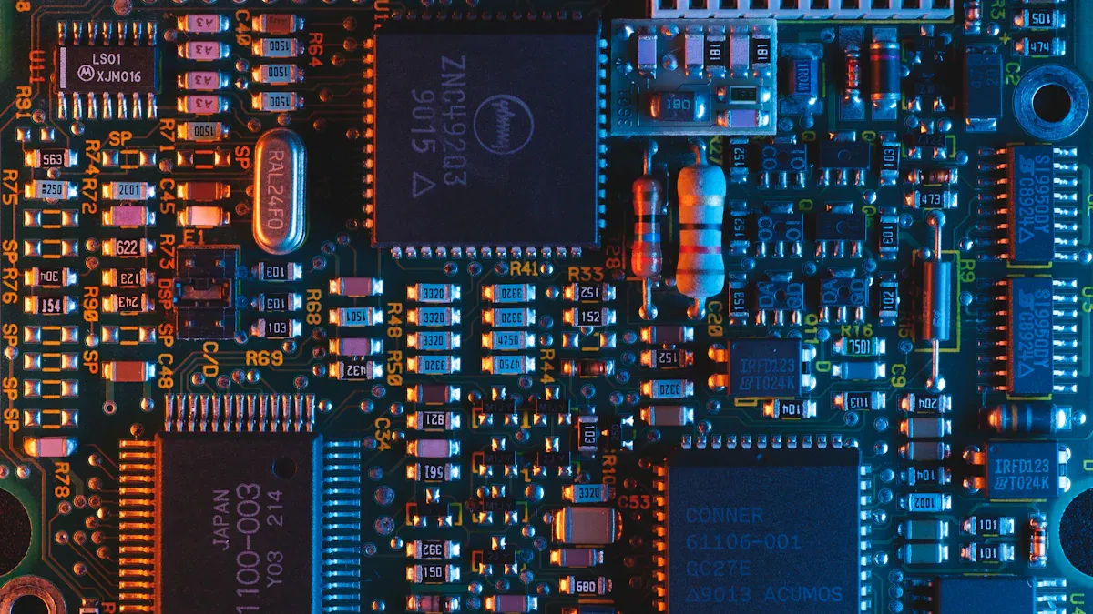
মাল্টি-লেয়ার স্ট্যাকআপ ব্যবহার করলে জিপিএস পিসিবি ডিজাইনের জন্য একটি শক্তিশালী ভিত্তি তৈরি হয়। একাধিক লেয়ার আপনাকে সিগন্যাল পাথ পরিচালনা করতে এবং ইন্টারফেরেন্স কমাতে সাহায্য করে। হাই-স্পিড ট্রেসগুলোকে পাওয়ার এবং গ্রাউন্ড প্লেন থেকে আলাদা করে জিপিএস-এর পারফরম্যান্স ও নির্ভুলতা উন্নত করা হয়। স্পষ্ট নেভিগেশন সিগন্যালের জন্য জিপিএস অ্যান্টেনাটি উপরের লেয়ারে রাখা হয়। নিচের টেবিলে একটি সাধারণ হাই-পারফরম্যান্স জিপিএস পিসিবি স্ট্যাকআপ দেখতে পারেন:
স্তর সংখ্যা | বিবরণ |
|---|---|
1 | উচ্চ-গতির সংকেত ট্রেস এবং উপাদান |
2 | স্থল সমতল |
3 | পাওয়ার প্লেন (যেমন, 3.3V) |
4 | পাওয়ার প্লেন (যেমন, 5V) |
5 | স্থল সমতল |
6 | অতিরিক্ত সিগন্যাল ট্রেস বা কম-গতির I/O |
সিগন্যাল পরিষ্কার রাখতে ও নয়েজ কমাতে এই কাঠামোটি ব্যবহার করা হয়। এটি জটিল জিপিএস সার্কিটের রাউটিংও সহজ করে তোলে।
গ্রাউন্ড এবং পাওয়ার প্লেন সেটআপ
সংবেদনশীল জিপিএস সংকেত সুরক্ষিত রাখতে আপনি গ্রাউন্ড এবং পাওয়ার প্লেন স্থাপন করেন। সংকেত স্তরগুলোকে হস্তক্ষেপ থেকে রক্ষা করার জন্য আপনি গ্রাউন্ড প্লেনগুলোকে সেগুলোর কাছাকাছি স্থাপন করেন। ক্রস-টক প্রতিরোধ করতে আপনি বিভিন্ন ভোল্টেজের জন্য আলাদা পাওয়ার প্লেন ব্যবহার করেন। জিপিএস অ্যান্টেনা এবং সংকেত ট্রেসের নিচে গ্রাউন্ড প্লেনটিকে অবিচ্ছিন্ন রাখা হয়। এই পদক্ষেপটি আপনাকে সংকেতের অখণ্ডতা বজায় রাখতে এবং জিপিএস-এর কর্মক্ষমতা বাড়াতে সাহায্য করে।
পরামর্শ: গ্রাউন্ড প্লেন বিভক্ত করা থেকে বিরত থাকুন। নির্ভরযোগ্য নেভিগেশন এবং জিএনএসএস অপারেশনের জন্য এগুলোকে অখণ্ড রাখুন।
অস্তরক উপাদান নির্বাচন
আপনার পিসিবি-তে সিগন্যাল লস কমানোর জন্য আপনি সঠিক ডাইইলেকট্রিক উপাদান বেছে নেন। উচ্চ-গতির জিপিএস সিগন্যালের জন্য আপনি কম ডাইইলেকট্রিক কনস্ট্যান্টযুক্ত উপাদান নির্বাচন করেন। এর মাধ্যমে আপনি পারফরম্যান্স উন্নত করেন এবং ট্রেসগুলোর মধ্যে ক্রসটক হ্রাস করেন। নিচের সারণিতে আপনি এই উপাদানগুলোর সুবিধাগুলো দেখতে পারেন:
সুবিধা | বিবরণ |
|---|---|
উচ্চ-গতির সংকেত প্রচার | নিম্ন ডাইইলেকট্রিক ধ্রুবকের কারণে ক্ষতি কম হয়। |
ক্রসটক হ্রাস | ট্রেস এবং ভায়াসের মধ্যে হস্তক্ষেপ কমিয়ে আনে |
ক্যাপাসিটিভ কাপলিং সীমাবদ্ধ করে | সার্কিটের জটিলতা কমায় এবং কর্মক্ষমতা উন্নত করে |
অমিল ট্রেস দৈর্ঘ্য | সমান্তরাল নেটওয়ার্কগুলিতে প্রতিকূল প্রভাব কমায় |
জিপিএস পিসিবি ডিজাইনের জন্য আপনি রজার্স ৪৩৫০বি, আরটি ডিউরয়েড ৫৮৮০, এবং আইসোলা-আই স্পিডের মতো উপাদান বেছে নেন । এই উপাদানগুলো আপনাকে শক্তিশালী সিগন্যাল কোয়ালিটি এবং নির্ভরযোগ্য জিপিএস নির্ভুলতা অর্জনে সহায়তা করে।
লেয়ার স্ট্যাকআপের উপর মনোযোগ দিলে আপনি এমন একটি জিপিএস পিসিবি তৈরি করতে পারেন যা শক্তিশালী নেভিগেশন এবং জিএনএসএস পারফরম্যান্স সমর্থন করে। এর মাধ্যমে আপনি সিগন্যাল সুরক্ষিত রাখেন, নয়েজ কমান এবং আপনার ডিভাইসকে নির্ভরযোগ্য রাখেন।
সিগন্যাল ইন্টিগ্রিটি এবং আরএফ পারফরম্যান্স
সর্বোত্তম নির্ভুলতা ও কর্মক্ষমতা অর্জনের জন্য আপনাকে জিপিএস সিগন্যালকে নয়েজ এবং ইন্টারফেরেন্স থেকে রক্ষা করতে হবে। একটি ভালো জিপিএস পিসিবি ডিজাইন সিগন্যালকে পরিষ্কার ও শক্তিশালী রাখতে সাহায্য করে। সিগন্যালের অখণ্ডতা উন্নত করতে এবং নির্ভরযোগ্য নেভিগেশন নিশ্চিত করতে আপনি বিভিন্ন কৌশল ব্যবহার করতে পারেন।
ইএমআই এবং ক্রসস্টক হ্রাস
ইলেক্ট্রোম্যাগনেটিক ইন্টারফারেন্স (EMI) এবং ক্রসটক জিপিএস সিগন্যালকে দুর্বল করে এবং নির্ভুলতা কমিয়ে দেয়। আপনার পিসিবি-তে EMI এবং ক্রসটক কমাতে আপনি এই পদক্ষেপগুলো নিতে পারেন :
পিসিবির এক প্রান্তে সমস্ত বাহ্যিক সংযোগ স্থাপন করুন। এই ব্যবস্থাটি আপনাকে নয়েজ নিয়ন্ত্রণ করতে এবং সিগন্যালগুলোকে সুসংগঠিত রাখতে সাহায্য করে।
প্রান্তের কাছাকাছি উচ্চ-গতির ট্রেস রাউটিং করা এড়িয়ে চলুন। এতে একটি ভালো রেফারেন্স গ্রাউন্ড বজায় থাকে এবং অবাঞ্ছিত নয়েজ প্রতিরোধ করা যায়।
কানেক্টরগুলোর মধ্যে উচ্চ-গতির সার্কিট থাকলে পিসিবি-টি একটি ধাতব চ্যাসিসে স্থাপন করুন। এই পদ্ধতিটি আবিষ্ট ভোল্টেজকে শর্ট সার্কিট করে এবং আপনার জিপিএস অ্যান্টেনা সুরক্ষিত রাখে।
হাই-স্পিড ট্রেসের কাছাকাছি I/O ট্রেস পরীক্ষা করুন। ক্রসটক শুরু হওয়ার আগেই তা বন্ধ করুন।
লো-ইম্পিডেন্স বন্ডের মাধ্যমে হিটসিঙ্কগুলিকে গ্রাউন্ড করুন। এই পদক্ষেপটি বৈদ্যুতিক ক্ষেত্রের কাপলিং কমায় এবং আপনার জিপিএস সংকেত পরিষ্কার রাখে।
এই পদক্ষেপগুলো অনুসরণ করলে আপনি জিপিএস-এর কর্মক্ষমতা উন্নত করতে এবং আপনার ডিভাইসকে আরও নির্ভরযোগ্য করে তুলতে পারবেন।
ওয়েভগাইড এবং ব্যাক-ড্রিলিং কৌশল
আপনার জিপিএস পিসিবি-তে আরএফ পারফরম্যান্স উন্নত করতে আপনি ওয়েভগাইড এবং ব্যাক-ড্রিলিং কৌশল ব্যবহার করতে পারেন। ব্যাক-ড্রিলিং ভায়াস-এর অব্যবহৃত অংশগুলো অপসারণ করে, যা সিগন্যাল প্রতিফলন এবং বিলম্ব কমাতে সাহায্য করে। এই পদ্ধতিটি উচ্চ-ফ্রিকোয়েন্সির জিপিএস সিগন্যালযুক্ত মাল্টি-লেয়ার পিসিবি-তে সবচেয়ে ভালো কাজ করে। উদাহরণস্বরূপ, যখন সিগন্যাল ফ্রিকোয়েন্সি ১৫ গিগাহার্টজ-এর উপরে যায়, তখন ব্যাক-ড্রিলিং সিগন্যাল বিলম্ব ১২ পিকোসেকেন্ড/ইঞ্চি থেকে ৫ পিকোসেকেন্ড/ইঞ্চিতে নামিয়ে আনতে পারে । এর ফলে আপনি দ্রুততর এবং পরিষ্কার জিপিএস সিগন্যাল পান, যা উন্নত নেভিগেশন এবং জিএনএসএস নির্ভুলতার দিকে পরিচালিত করে। সিঙ্গেল বা ডাবল-লেয়ার বোর্ডের ক্ষেত্রে, খরচের তুলনায় ব্যাক-ড্রিলিং যথেষ্ট সুবিধা নাও দিতে পারে।
শিল্ডিং এবং ডিকাপলিং
শিল্ডিং এবং ডিকাপলিং আপনার জিপিএস সার্কিটকে নয়েজ ও ইন্টারফেরেন্স থেকে রক্ষা করে। আপনার জিপিএস পিসিবি ডিজাইনকে শক্তিশালী রাখতে আপনি এই পদ্ধতিগুলো ব্যবহার করতে পারেন:
বাইরের কোলাহল রোধ করতে ধাতব বেষ্টনী এবং গ্রাউন্ড প্লেন ব্যবহার করুন ।
পিসিবি-স্তরের শিল্ড এবং পরিবাহী ক্যান ব্যবহার করে গুরুত্বপূর্ণ সার্কিটগুলোকে বিচ্ছিন্ন করুন।
আইসোলেশন কৌশল ব্যবহার করে নয়েজের বিস্তার রোধ করুন।
উচ্চ-ফ্রিকোয়েন্সি ফিল্টারিংয়ের জন্য কম লিড ইন্ডাকট্যান্সযুক্ত ফিড-থ্রু বা স্ট্যান্ড-অফ ক্যাপাসিটর বেছে নিন।
যেসব সার্কিটে উচ্চ রিপল বা ভোল্টেজ পরিবর্তন হয়, সেখানে সলিড-স্টেট ক্যাপাসিটর ব্যবহার করুন।
এই পদক্ষেপগুলো আপনাকে সিগন্যালের মান বজায় রাখতে এবং জিপিএস-এর কর্মক্ষমতা উন্নত করতে সাহায্য করে। আপনার জিপিএস অ্যান্টেনা থেকে নয়েজ দূরে রাখার মাধ্যমে আপনি নির্ভরযোগ্য নেভিগেশন এবং শক্তিশালী জিএনএসএস অপারেশন নিশ্চিত করেন।
জিপিএস পিসিবি-র জন্য রাউটিং কৌশল
নিয়ন্ত্রিত প্রতিবন্ধকতা রাউটিং
কন্ট্রোলড ইম্পিডেন্স রাউটিং ব্যবহার করলে জিপিএস পিসিবি-র পারফরম্যান্স উন্নত হয়। এই সেরা পদ্ধতিগুলো অনুসরণ করে সিগন্যাল পরিষ্কার ও শক্তিশালী রাখা যায়:
উচ্চ-গতির ট্রেসগুলির নিচে একটি স্থির রেফারেন্স প্লেন বজায় রাখুন । এই পদক্ষেপটি সিগন্যালের প্রত্যাবর্তন পথকে সাহায্য করে এবং নয়েজ এড়ায়।
স্প্লিট প্লেনের উপর দিয়ে ট্রেস রাউটিং করা পরিহার করুন। সিগন্যাল রিটার্ন পাথ ট্রেসটিকে অনুসরণ করতে পারে না, যার ফলে ইএমআই (EMI) হয় এবং জিপিএস পারফরম্যান্স দুর্বল হয়ে পড়ে।
সঠিক ট্রেস প্রস্থ এবং ব্যবধান বজায় রাখুন। 3W নিয়মটি ব্যবহার করুন, যেখানে গ্রাউন্ড প্লেনটি প্রতিটি পাশে ট্রেস প্রস্থের অন্তত তিনগুণ হতে হবে।
ডিফারেনশিয়াল পেয়ারগুলোর ট্রেস লেংথ মেলান। এর মাধ্যমে আপনি প্রোপাগেশন ডিলে মিসম্যাচ কমিয়ে আনেন এবং জিপিএস সিগন্যাল নির্ভুল রাখেন।
এই ধাপগুলো অনুসরণ করলে আপনি নির্ভরযোগ্য নেভিগেশন এবং শক্তিশালী জিএনএসএস অপারেশন নিশ্চিত করতে পারবেন।
ট্রেস দৈর্ঘ্য অপ্টিমাইজেশান
আপনার পিসিবি-তে ট্রেসের দৈর্ঘ্য অপ্টিমাইজ করার মাধ্যমে আপনি জিপিএস-এর নির্ভুলতা বাড়াতে পারেন। ছোট ট্রেস সিগন্যালকে দ্রুত চলাচল করতে সাহায্য করে এবং ত্রুটি কমায়। আপনি সিগন্যাল ইন্টিগ্রিটি উচ্চ রাখেন, যা জিপিএস সিস্টেমের জন্য টাইমিং এবং পজিশনিং নির্ভুলতা উন্নত করে । আপনি আপনার ডিভাইসকে আরও নির্ভরযোগ্য করে তোলেন। আপনি জিপিএস সিগন্যালের উপর নির্ভরশীল সিস্টেমগুলিতে অপ্রত্যাশিত ব্যর্থতা প্রতিরোধ করেন। আপনি সিস্টেমের কার্যকারিতা বৃদ্ধি করেন, কারণ আপনি সিগন্যাল পুনঃপ্রেরণের প্রয়োজনীয়তা হ্রাস করেন এবং ত্রুটি কমিয়ে আনেন।
পরামর্শ: আপনার জিপিএস ট্রেস যতটা সম্ভব সংক্ষিপ্ত এবং সরাসরি রাখুন। এতে আপনার জিপিএস অ্যান্টেনা নির্ভুল দিকনির্দেশনার জন্য স্পষ্ট সংকেত পাঠাতে সাহায্য করে।
উচ্চ-ঘনত্বের সংকেত পথ
আপনার জিপিএস পিসিবিতে উচ্চ-ঘনত্বের সিগন্যাল পাথ রাউট করার সময় আপনি বিভিন্ন চ্যালেঞ্জের সম্মুখীন হন। সেগুলো কাটিয়ে উঠতে আপনি এই কৌশলগুলো ব্যবহার করতে পারেন:
ট্রেসগুলো ছোট ও সোজা রাখুন। এতে ভুল ও প্রতিফলন কমে যায়।
একটি সলিড গ্রাউন্ড প্লেনের উপর দিয়ে উচ্চ-গতির সিগন্যাল প্রেরণ করুন। এতে সিগন্যালের অখণ্ডতা বজায় থাকে।
ট্রেসগুলোর মধ্যে ব্যবধান বাড়ান। এতে ক্রসটক কমে যায়।
ডিফারেনশিয়াল পেয়ারগুলোর ট্রেস লেংথ মেলান। এতে স্কিউ এড়ানো যায় এবং জিপিএস সিগন্যাল নির্ভুল থাকে।
পাওয়ার সেকশনের কাছাকাছি উচ্চ-গতির সংকেত পাঠানো এড়িয়ে চলুন। এতে হস্তক্ষেপ প্রতিরোধ করা যায়।
এই রাউটিং কৌশলগুলো ব্যবহার করলে আপনি এমন একটি পিসিবি তৈরি করতে পারেন যা শক্তিশালী জিপিএস পারফরম্যান্স এবং নির্ভরযোগ্য নেভিগেশন সমর্থন করে।
জিপিএস পিসিবি পারফরম্যান্সের জন্য উৎপাদন
উপাদান এবং সহনশীলতার পছন্দ
শক্তিশালী জিপিএস পারফরম্যান্স পেতে আপনাকে সঠিক উপাদান নির্বাচন করতে হবে। আপনার নির্বাচিত উপাদান সিগন্যালের গুণমান এবং নির্ভরযোগ্যতাকে প্রভাবিত করে। কিছু উপাদান উচ্চ-ফ্রিকোয়েন্সির জিপিএস অ্যাপ্লিকেশনের জন্য ভালোভাবে কাজ করে। আপনি নিচের টেবিলে প্রধান বিকল্পগুলো দেখতে পারেন :
উপাদান প্রকার | কী বৈশিষ্ট্যাবলী | সেরা ব্যবহারের ক্ষেত্রে |
|---|---|---|
উচ্চ-Tg FR-4 | উচ্চ গ্লাস ট্রানজিশন তাপমাত্রা, মাঝারি ডাইইলেকট্রিক ধ্রুবক | ভোক্তা-স্তরের স্বয়ংচালিত জিপিএস ইউনিট |
PTFE-ভিত্তিক ল্যামিনেটস | নিম্ন ডাইইলেকট্রিক ধ্রুবক, খুব কম ক্ষতি | উচ্চ-ফ্রিকোয়েন্সি জিপিএস এবং রাডার সিস্টেম |
সিরামিক-ভরা উপকরণ | নিম্ন ডাইইলেকট্রিক ধ্রুবক, উচ্চ তাপ পরিবাহিতা | মহাকাশ এবং সামরিক নেভিগেশন সিস্টেম |
পলিমাইড | চমৎকার তাপীয় স্থিতিশীলতা, কম প্রসারণ | সামুদ্রিক বা মহাকাশ নেভিগেশন সিস্টেম |
আপনার উৎপাদন সহনশীলতার দিকেও মনোযোগ দেওয়া উচিত। কঠোর সহনশীলতা সিগন্যাল পাথকে নির্ভুল রাখতে সাহায্য করে। এই পদক্ষেপটি জিপিএস পিসিবির ধারাবাহিক কর্মক্ষমতা নিশ্চিত করে।
ডিএফএম এবং টেস্টিং
ডিজাইন ফর ম্যানুফ্যাকচারেবিলিটি (ডিএফএম) এর সেরা পদ্ধতিগুলো ব্যবহার করলে আপনার পিসিবি উৎপাদন উন্নত হয়। আপনার ডিজাইন প্রক্রিয়ার শুরুতেই ডিএফএম শুরু করুন। ব্যয়বহুল ভুল এড়াতে প্রতিটি পর্যায়ে আপনার ডিজাইন পরীক্ষা করুন। এই পরামর্শগুলো অনুসরণ করুন:
ত্রুটির জন্য আপনার স্কিম্যাটিক, কম্পোনেন্ট প্লেসমেন্ট এবং রাউটিং পর্যালোচনা করুন।
ড্রিল করা গর্ত এবং তামার ট্রেসের মধ্যে পর্যাপ্ত জায়গা রাখুন।
ছিদ্র এবং বোর্ডের পুরুত্বের জন্য সঠিক আকৃতির অনুপাত ব্যবহার করুন।
চূড়ান্ত অনুমোদনের আগে ডিএফএম বিশ্লেষণ চালান।
এই পদক্ষেপগুলো আপনাকে খরচ কমাতে, নির্ভরযোগ্যতা বাড়াতে এবং বাজারে পণ্য আনার সময় কমাতে সাহায্য করে । ব্যাপক উৎপাদনের আগে আপনাকে আপনার জিপিএস পিসিবি পরীক্ষাও করতে হবে। গুরুত্বপূর্ণ পরীক্ষাগুলোর মধ্যে রয়েছে :
পাওয়ার-অন পরীক্ষা
জিএনএসএস সংকেত পরীক্ষা
অ্যান্টেনা সংযোগ পরীক্ষা
তাপমাত্রা সাইক্লিং পরীক্ষা
কম্পন পরীক্ষা
চূড়ান্ত কার্যকারিতা পরীক্ষা
বহিরাঙ্গন ও মোবাইল ডিভাইসগুলোর জন্য অতিরিক্ত পরীক্ষা-নিরীক্ষার প্রয়োজন। বৃহৎ পরিসরে উৎপাদনের আগে তাপমাত্রার পরিবর্তন, কম্পন, ব্যাটারির আচরণ এবং ওয়্যারলেসের স্থিতিশীলতা পরীক্ষা করে নিন।
গুণগত মান
আপনার জিপিএস পিসিবি নির্ভরযোগ্য রাখতে আপনাকে অবশ্যই শক্তিশালী গুণমান নিশ্চিতকরণ পদ্ধতি ব্যবহার করতে হবে। ম্যানুয়াল এবং স্বয়ংক্রিয় উভয় পরিদর্শনই ব্যবহার করুন। নিচের সারণিতে সাধারণ গুণমান পরীক্ষাগুলো দেখানো হলো :
পরীক্ষার পদ্ধতি | বিবরণ |
|---|---|
ইন-সার্কিট টেস্টিং (আইসিটি) | সার্কিটে ওপেন বা শর্ট সার্কিট আছে কিনা তা পরীক্ষা করে। |
ফ্লাইং প্রোব টেস্ট | বিদ্যুৎ ছাড়াই আলগা সংযোগ খুঁজে বের করে। |
কার্যকরী পরীক্ষা | নিশ্চিত করে যে পিসিবিটি প্রত্যাশা অনুযায়ী কাজ করছে। |
স্বয়ংক্রিয় অপটিক্যাল পরিদর্শন | ক্যামেরা ব্যবহার করে অনুপস্থিত যন্ত্রাংশ বা ঝালাইয়ের সমস্যা খুঁজে বের করে। |
এক্স-রে পরিদর্শন | পিসিবির ভিতরে লুকানো শর্ট বা ফাঁক আছে কিনা তা দেখা হয়। |
বৈদ্যুতিক পরীক্ষা | কর্মক্ষমতা যাচাই করার জন্য আউটপুট সংকেত পরিমাপ করে। |
চাক্ষুষ পরিদর্শন | এমন শারীরিক ক্ষতি খুঁজে পায় যা কর্মক্ষমতাকে ক্ষতিগ্রস্ত করতে পারে। |
আপনার কম্পোনেন্ট এবং অ্যাসেম্বলির ধাপগুলোও ট্র্যাক করা উচিত। এই ট্রেসেবিলিটি আপনাকে দ্রুত সমস্যা খুঁজে বের করতে ও সমাধান করতে সাহায্য করে। যখন আপনি এই ধাপগুলোকে শক্তিশালী জিএনএসএস ইন্টিগ্রেশনের সাথে যুক্ত করেন, তখন আপনি আরও ভালো পজিশনিং অ্যাকুরেসি এবং আরও শক্তিশালী সিগন্যাল নির্ভরযোগ্যতা পান । আপনার জিপিএস পিসিবি প্রতিকূল পরিবেশেও ভালোভাবে কাজ করবে।
অ্যান্টেনার সঠিক অবস্থান, সিগন্যালের অখণ্ডতা এবং সতর্ক উৎপাদনের উপর মনোযোগ দিলে আপনি জিপিএস-এর সর্বোত্তম কার্যকারিতা অর্জন করতে পারেন। ক্ষয় এবং বৈদ্যুতিক সমস্যা প্রতিরোধ করে এমন উপকরণ নির্বাচন করার জন্য ডেটাশিটের নির্দেশিকা অনুসরণ করুন। আপনার ডিজাইন যাচাই করার জন্য সিমুলেশন এবং টেস্টিং ব্যবহার করুন। অ্যান্টেনা ইন্টিগ্রেশন এবং উন্নত শিল্ডিং-এর মতো সাম্প্রতিক অগ্রগতিগুলো আপনাকে নির্ভরযোগ্য জিপিএস ডিভাইস তৈরি করতে সাহায্য করে। ISO 9001 এবং ISO 9100-এর মতো শিল্প মানগুলো গুণমান এবং নির্ভুলতা নিশ্চিত করে। আপনার দক্ষতা ক্রমাগত উন্নত করতে থাকুন এবং সেরা ফলাফলের জন্য প্রতিটি খুঁটিনাটি বিষয়ে মনোযোগ দিন।
মান | উদ্দেশ্য | জিপিএস পিসিবি-র উপর প্রভাব |
|---|---|---|
আইএসও 9001 | গুনগত পরিচালনা পদ্ধতি | নির্ভরযোগ্যতা এবং নির্ভুলতা নিশ্চিত করে |
আইএসও 9100 | মহাকাশ গুণমান ব্যবস্থাপনা | উচ্চ মান বজায় রাখে |
FAQ
জিপিএস পিসিবি-র কর্মক্ষমতার জন্য সবচেয়ে গুরুত্বপূর্ণ বিষয় কোনটি?
অ্যান্টেনার অবস্থান সবচেয়ে গুরুত্বপূর্ণ। অ্যান্টেনাটি উপরের স্তরে এবং কোলাহলপূর্ণ অংশ থেকে দূরে রাখা উচিত। এই পদক্ষেপটি আপনাকে স্পষ্ট সংকেত এবং উন্নত জিপিএস নির্ভুলতা পেতে সাহায্য করে।
একটি জিপিএস পিসিবি-তে নয়েজ কীভাবে কমানো যায়?
আপনি করতে পারেন:
দৃঢ় ভূমি তল ব্যবহার করুন।
চিহ্নগুলি সংক্ষিপ্ত রাখুন।
সংবেদনশীল সার্কিটগুলোর চারপাশে সুরক্ষা আবরণ যুক্ত করুন।
এই পদক্ষেপগুলো আপনাকে হস্তক্ষেপ রোধ করতে এবং সংকেত পরিষ্কার রাখতে সাহায্য করে।
উচ্চ-ফ্রিকোয়েন্সি জিপিএস পিসিবি-র জন্য কোন উপাদানগুলো সবচেয়ে ভালো কাজ করে?
উপাদান | সুবিধা |
|---|---|
পিটিএফই ল্যামিনেট | কম সংকেত ক্ষতি |
সিরামিক-ভরা | উচ্চ তাপ স্থায়িত্ব |
উচ্চ-Tg FR-4 | বেশিরভাগ ব্যবহারের জন্য ভালো |
আপনার ডিভাইসের প্রয়োজন অনুযায়ী উপকরণ নির্বাচন করা উচিত।
আপনার কেন ডেটাশিট নির্দেশিকা অনুসরণ করা উচিত?
ডেটাশিটের নিয়মকানুন অনুসরণ করলে সেরা ফলাফল পাওয়া যায়। এই নির্দেশিকাগুলো আপনাকে সঠিক ট্রেস উইডথ, স্পেসিং এবং লেআউট দেখায়। এর মাধ্যমে আপনি ভুল এড়াতে পারেন এবং জিপিএস-এর নির্ভরযোগ্যতা বাড়াতে পারেন।